This article covers how to install a Z Grills Australia Wireless controller in a 450A or 700 series pellet smoker.
For Grill Models: 450A, 7002B, 700E, 700E-XL
Time: 20-30min
Difficulty: Medium
Spare Parts (from Z Grills):
- WIFI Controller
- WIFI Antenna
- Cable Ties
- Kep Nut
Tools Required:
- Pliers or small socket set
- Phillips head screwdriver
- Scissors or knife
Click here for Wireless Controller information.
Any questions about how to complete the process please contact us.
Wiring Connections
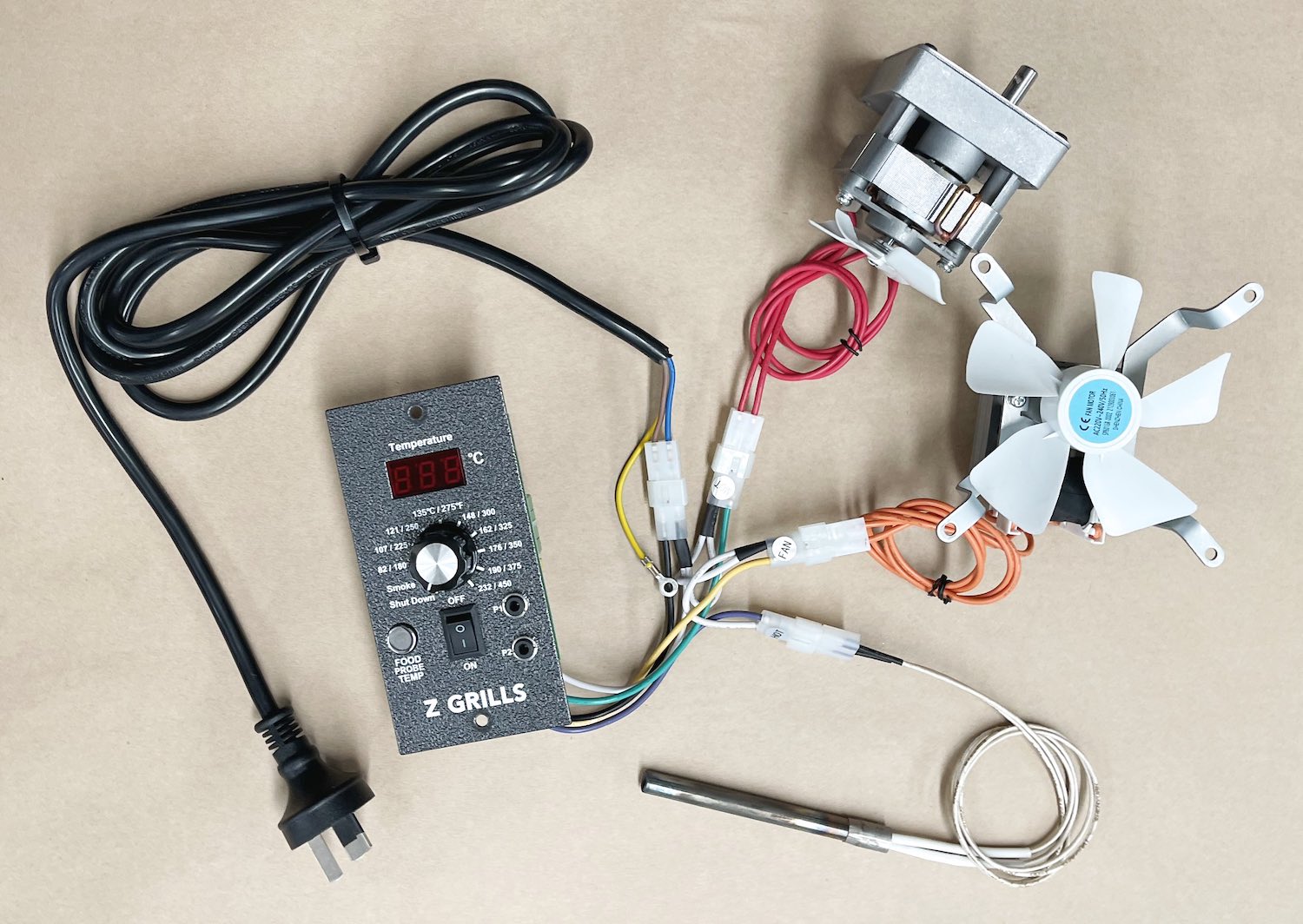
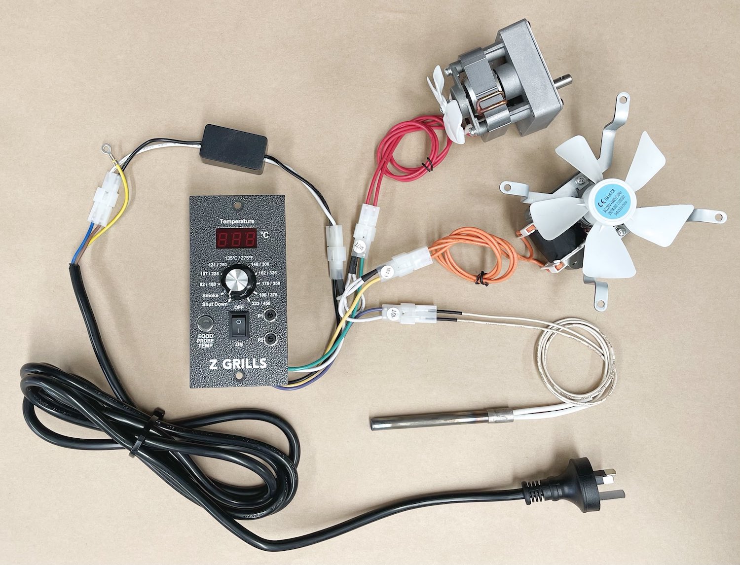
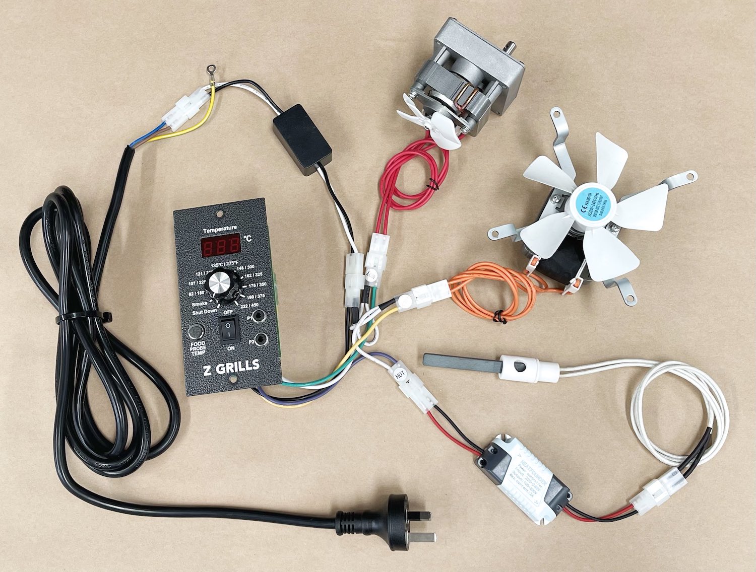
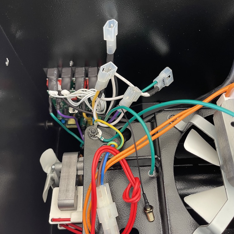
Depending on the grill model, the wiring colour and configuration may differ slightly. Refer to the images below to see the configuration that most closely matches your grill. Of key importance is being able to clearly identify the key components.
The controller 3 output plugs are labeled MOT (auger motor), FAN (big fan) and HOT (ignition rod).
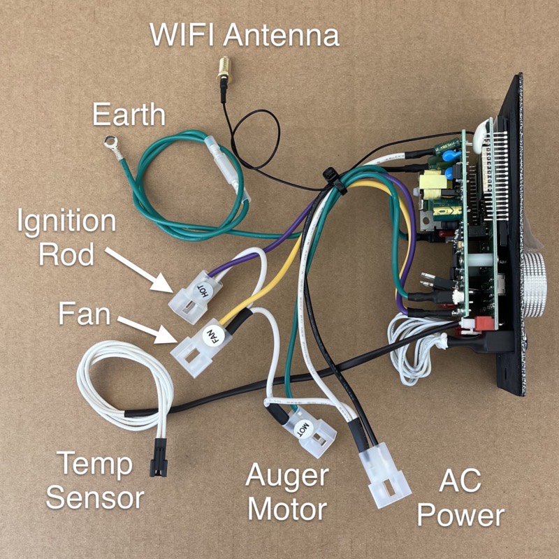
WIFI Controller Wiring
If replacing the basic PID controller with a new WIFI controller the mains plugs are the same, but the WIFI controller also adds a green earth wire and WIFI antenna cable.
The green earth wire should be attached on the same screw as the mains power earth (yellow-green wire). Instructions will be provided on this further down in Step 4.
Replacement Process
Step 1. Remove Hopper
Why Remove the Hopper?
While the controller can be replaced with the hopper still attached to the grill, it is much easier to lift the hopper assembly off the grill and place it up-side-down on a table. It will give much clearer access to the controller, cables and allow everything to be neatly tied once done.
If you decide to leave the hopper on the grill and access from below, or by taking the cover off, ensure that cables are suitably organised and tied in place. Failure to do so could damage the cables or controller.
Vacuum out all pellets from the hopper and ash from the fire-pot before removing!
Hopper Bolts
The hopper can be removed by undoing the 4 bolts on the inside left of the grill drum. The bolts in the 450A may be quite tight, so a socket wrench would be advisable.
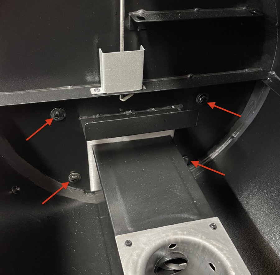
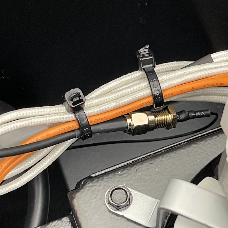
Temperature Sensor Plug
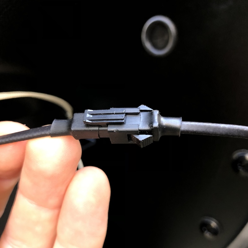
Don’t forget to unplug the temperature sensor cable that is tucked between the hopper and grill drum.
If the 450A temperature sensor cable does not have a plug in the middle it will need to be cut. In this case a new sensor is required, and should have been supplied with the controller.
Step 2. Remove Bottom Cover
700 Series Grills
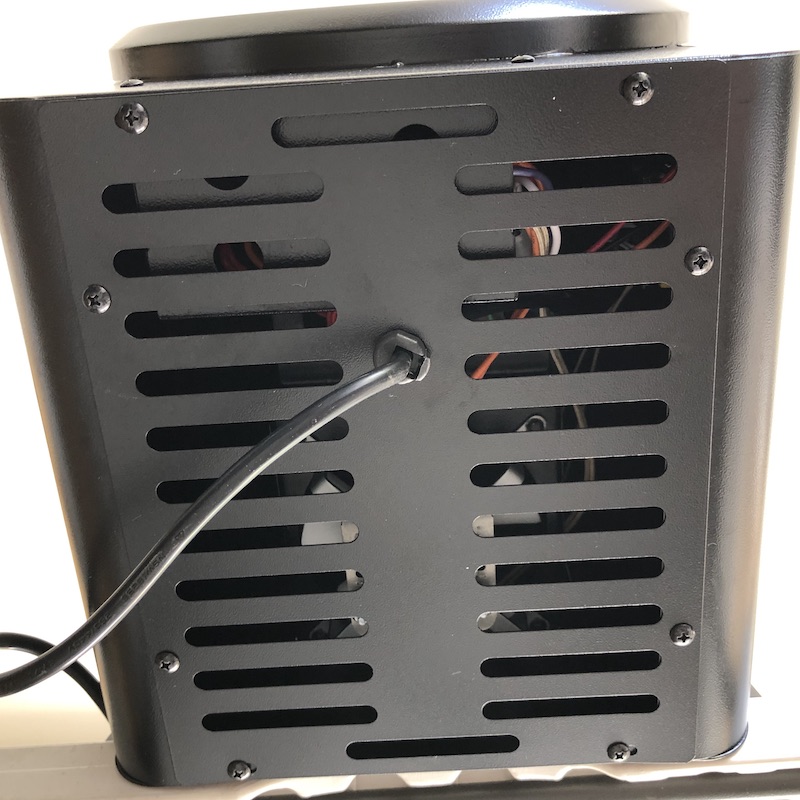
Remove the 6 screws on the front/rear/side of 700 series grill to lift the cover up.
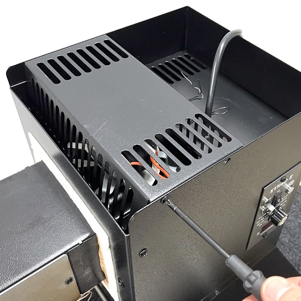
The power cable may not allow the cover to be fully lift out, in which case it can be tiled to the side.
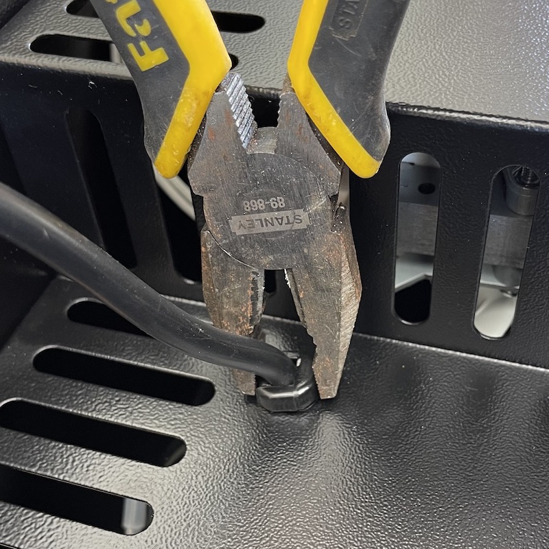
For even easier access, use a pair of wide nose pliers to compress and pop out the cable gland. Squeeze in with force the part of the gland that extends out the side, wiggle and pull on the cable at the same time. The power cable can then be freely fed through the bottom cover. Don’t lose the cable gland, as it should be put back at the end of the process.

450A Grills
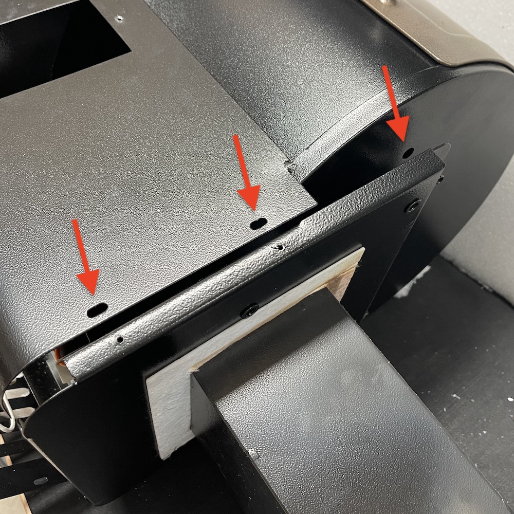
Remove the 8 screws on to remove the bottom cover. The two screws securing the little metal box housing the cable bundle can also be removed to allow the cables to be more easily accessed.
Remove the two side screws and screws inside the hopper to allow a gap to feed the temperature sensor cable through.
Step 3. Remove Old Controller
Release Cables
Using scissors or snips (not a knife) cut all the cable ties to free up the cables.
Unplug all plugs. Don’t worry about the colours and keeping tracking of the cables, as they are very easy to identify.
Remove Controller
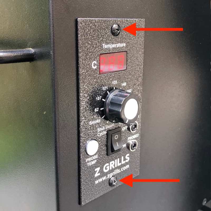
Remove the 2 screws in the front of the controller and gently pull it out.
Some 450A temperature sensor cables do not have a plug in the middle. In this case you should have been provided with a new temperature sensor cable along with the new controller. The existing sensor cable can be cut to allow the controller to be removed.
Refer to these instructions to install a new 450A temperature sensor.
Step 4. Install New WIFI Controller
Install Controller
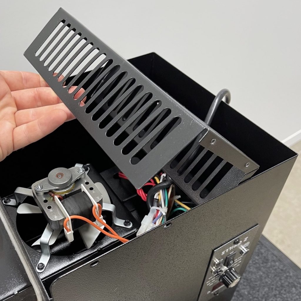
Pass the controller through the hole in the casing, guiding the cables up for good access. Keep the cables away from the auger motor with the small fan at the front.
Secure the controller in place with the two screws. Do not overtighten!
Step 5. Connect Cables
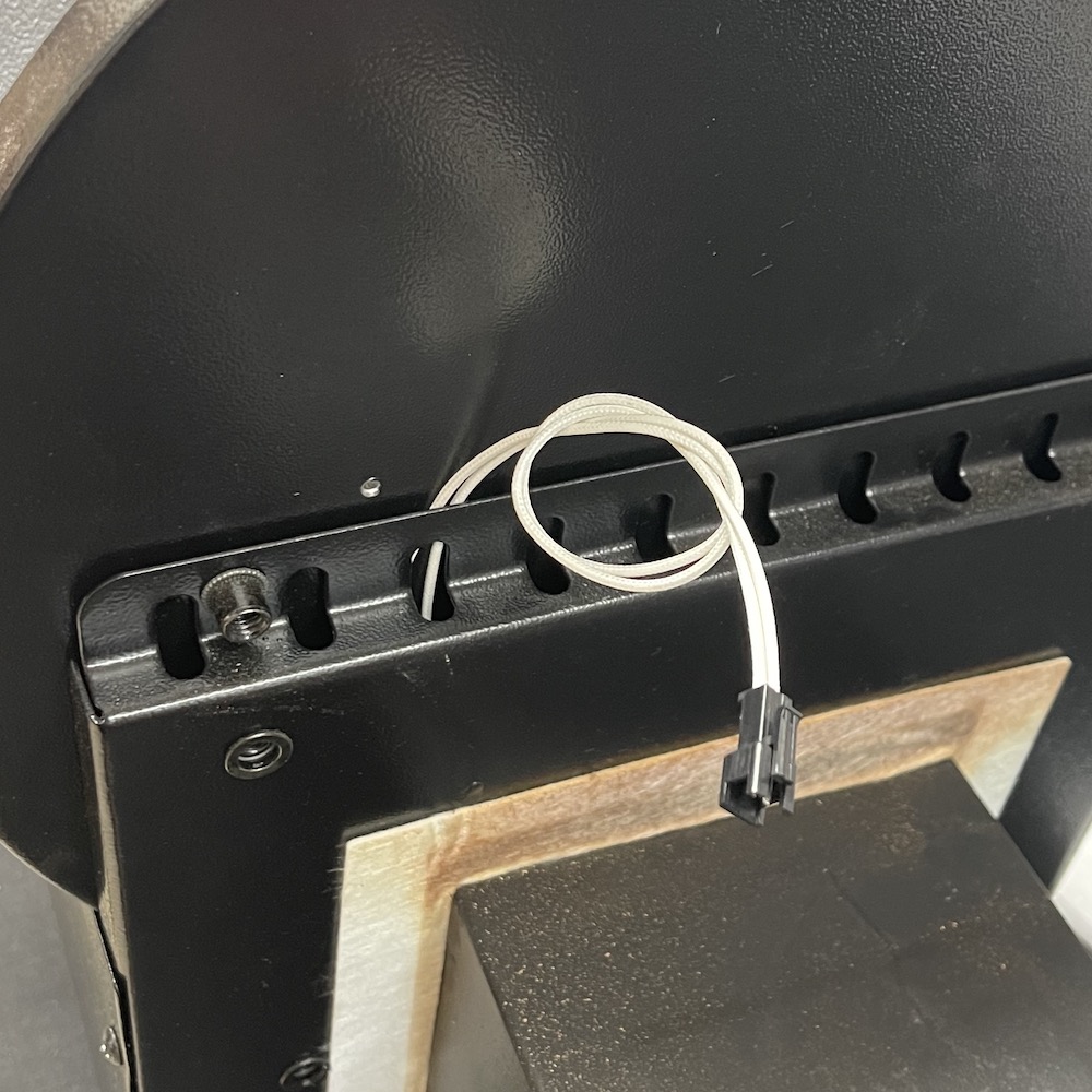
Temperature Sensor
Tuck the temperature sensor cable down and out the right hand side, following the same path of the previous temperature sensor thin white wires
Later this will plug into the temperature sensor cable that runs from the grill.
450A Grills: The plug won’t fit through the holes in the metal plate, so run between the hopper and metal plate.
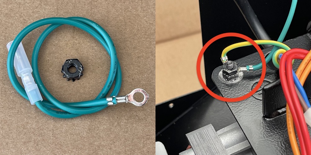
Earth Wire
WIFI controller includes a dedicated green earth wire. Secure the ring with the supplied kep nut onto the same threaded bolt that the main earth is attached. If the existing bolt is too short, loosen and use the existing kep nut.
Can’t find the kep nut? It maybe stuck to the magnet on the bottom of the antenna!
AC Power, Auger, Fan & Ignition Rod Plugs
Connect all the white plugs. The colour of the wires in your grill for the Fan and Auger motor may be different to the photos below, so make sure the cables are running to the correct device.
Auger motor (MOT) has a little fan on the front for cooling the motor, not be be confused with the BIG fan (FAN) that feeds the fire-pot with air flow.
Refer to the these wiring connection images so you are 100% clear on the components.
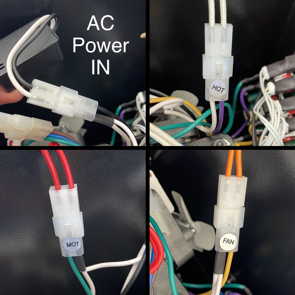
AC POWER SUPPLY
- From AC Power: brown-blue wires or
- Black Power Filter Box: white-black wires (not all grill have this black filter box). This is installed between the brown-blue wires plug and the white-white-black plug to the controller.
- To Controller: white-white-black wires
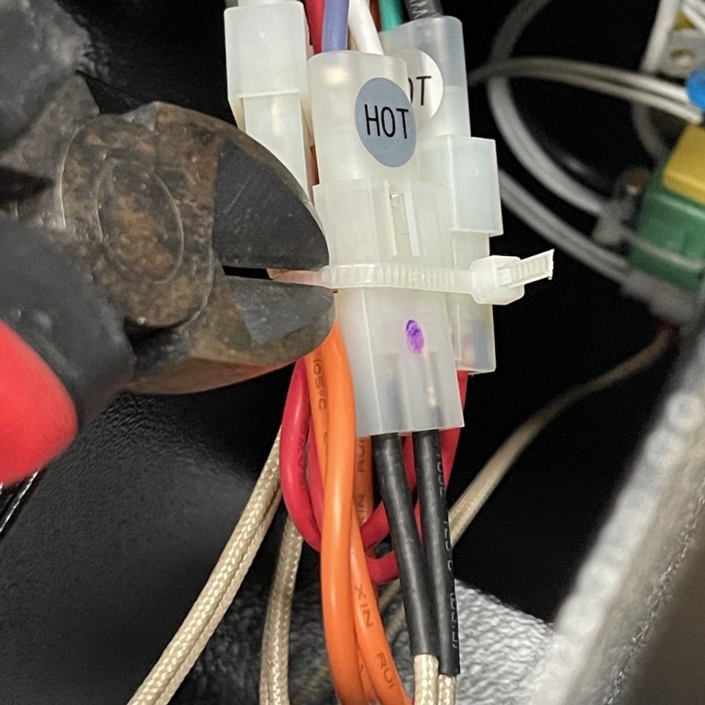
IGNITION ROD
- From Controller “HOT” labelled plug: white-purple wires
- To Ignition Rod: white-white thick high temperature wires
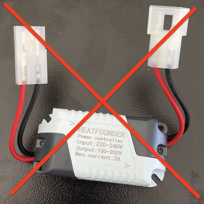
- If there is a light blue and black box attached to the ignition rod cable, (shown below) remove it altogether. It is no longer required.
FIRE-POT FAN (big fan)
- From Controller: “FAN” labelled: white-white-yellow wires
- To Fan Motor: normally orange-orange or black-black wires
AUGER MOTOR (small fan)
- From Controller: “MOT” labelled: white-white-green wires
- To Auger Motor: normally red-red or black-black wires
Note the auger motor should be very very loose!
Step 6. Clean up Cables
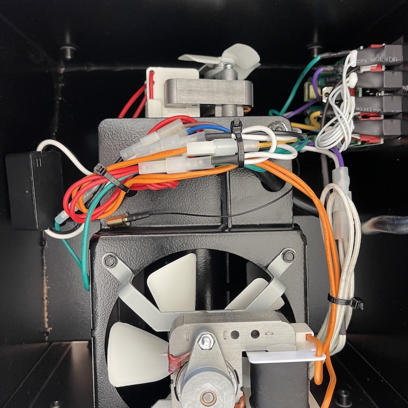
The cables needs to be neatly secured away from the auger motor (little fan) and the big fire-pot fan. Bundle them together as shown in the photo below and use the supplied cable ties. Do not over-tighten the cable ties!
The round holes in the metal plate can be used as anchors. This is particularly useful on the side furthest from the controller as shown in the image below (left side of photo).
Do not worry about securing the WIFI antenna cable yet.
Ensure the cables are not close to the auger motor fan!
WIFI Antenna Cable
Pass the brass nut end of the Antenna cable through a hole in the bottom cover next to the power cable.
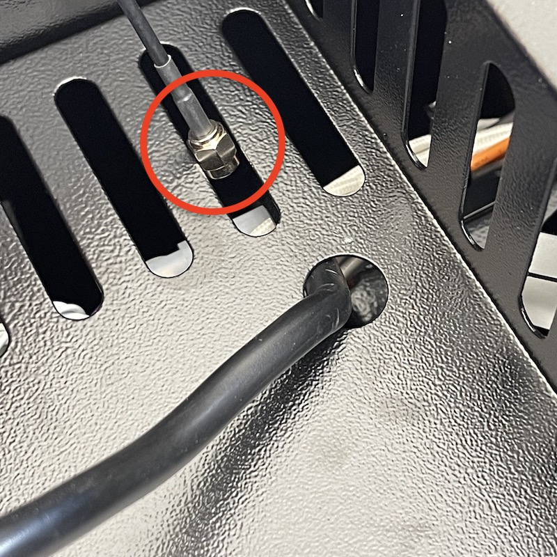
Carefully screw the nut onto the end of the threaded brass nut on the end of the thin black cable. Rotate the nut on the thick antenna cable and NOT the thin nut. The thread is very fine, so do this carefully to avoid crossing the thread. Finger tight is sufficient, do not put a spanner on this nut!
Gently loop the thin antenna wire around (do not kink it!) and cable tie behind the nut on the thicker cable as shown below.
Step 7. Replace Bottom Cover
Put the bottom cover back in place while carefully feeding the antenna and power cables back through. Leave some slack in both these cables underneath the cover.
Secure the bottom cover in place with the screws.
If the power cable gland was removed, push it back into place. If you have destroyed or lost the cable gland, don’t worry, just cable tie the power cable to the bottom of the cover in a couple of places.
Step 8. Operating Test
While the hopper is still removed from the grill a quick test can be completed to ensure everything is working properly.
To test the grill properly the temperature sensor will need to be plugged in, so if possible get the hopper close enough to the grill to connect the temperature sensor cable.
Basic Power On Test (no temp sensor)
- If the temperature sensor is NOT connected, a basic power on test can be completed.
- Plug the grill into power and press the controller button once . The screen will flash, show the software version and then display Error 1, running the the fan and sounding 3 beeps.
- Unplug the grill from power.
Operation Test (temp sensor plugged in)
- If the controller has the temperature sensor plug connected it can be tested even if sitting on the table. Do not run for more than 30 seconds as otherwise an unsafe fire may be established in the fire-pot.
- Sit the hopper upright in the normal orientation, ensure the power cable is not being squashed under the edge of of the box – place a screwdriver handle, folded up rag or similar to make enough space for the cable.
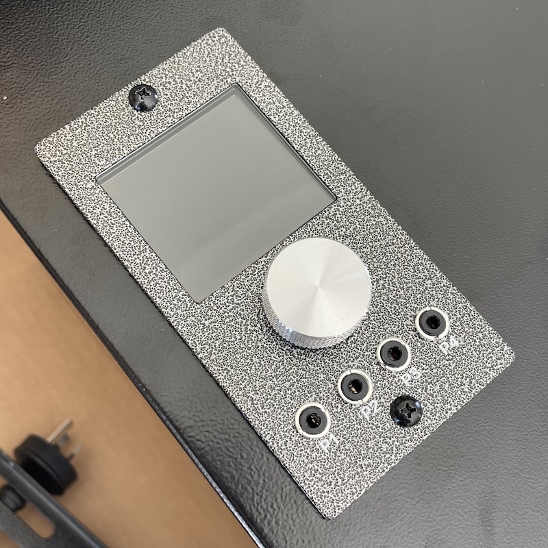
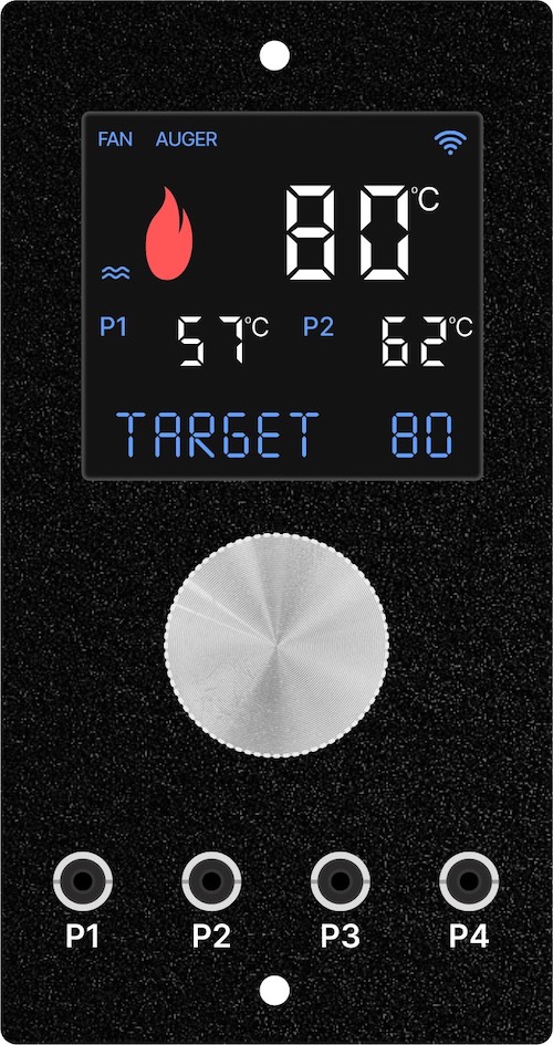
- Plug the power cable in press the control knob once to wake up the screen.
- The screen will flash everything and then the grill model and software version.
- To test the operation, press and hold the control knob for 2 seconds to enter the MENU, rotate clockwise on click to FIRE UP and the Fan, Auger Motor and Ignition Rod will all turn on.
- Listen to hear the fan blowing
- Look to see the auger motor slowing turning (will turn on and off). The display will show the word AUGER when it is on.
- Look (and feel for hot air) to see if the ignition rod is getting hot
- After confirming these are working correctly, unplug the controller from power (no need to shut down). Next, reinstall the hopper back into the grill.
Buzzing Noise?
If there is a buzzing noise look through the bottom cover to ensure no cables are close to the auger motor small fan or the big fire-pot fan.
Not Working?
If something isn’t operating as expected, double check all the plugged connections and if still not working correctly please contact us.
Step 9. Return Hopper to Grill
Partially slide the hopper back into the grill.
Connect the temperature sensor cable, bundling together and use a twist tie to cable tie to tie neatly. Tuck this down between the hopper and grill.
Slide the hopper all the way in and do up the 4 bolts. Do NOT over-torque the bolts as you can break the grip of the nutsert to the drum resulting in it spinning around!
It is now time to connect the grill to the App and install to the latest version (if available). Then you can fire the grill up as normal. No burn in is needed.
Step 10. Connect to App & Update Software
It is now time to connect the grill to the App and install to the latest grill software version (if available).
You can then fire the grill up as normal. No burn in is needed.
Controller and App Instructions
Now it’s time to learn how to use your fancy new controller and App!
Click here to learn how to use the WIFI controller.
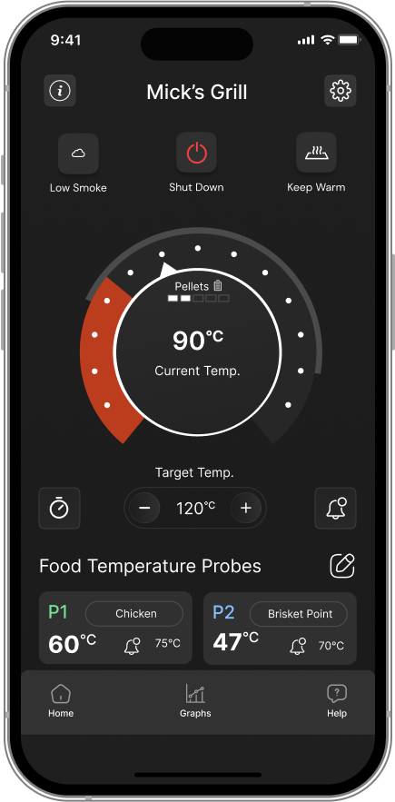
Click here to download and learn how to use the App to remotely monitor and control your grill.